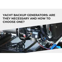
Practical experience of using the Simarine monitoring system convinced the topRik team that this is a set of high-quality battery monitors, patch panels, unique shunts and innovative modules with a long service life. This is evidenced by the three-year warranty period that the manufacturer provides for its products. But this is electrical and electronic equipment that is mounted on a yacht or camper; the entire period of operation is in an aggressive environment - constant vibration, salt water, high humidity or road dust, etc. Add here errors during installation and operation, neglect of technical inspection, overload of the monitoring system - and you will get the whole list of reasons why problems may occur in the system or its components.
topRik experts answer your questions about possible problems with your yacht tank level module and how to fix them. For example, we have chosen Simarine models and shunts, which have the function of measuring the state of the liquid level in all types of yacht tanks: SC503 and SC303, Quadro shunt and tank module SCQ25T, tank level module ST107.
1. What are the most common problems with tank level modules on yachts?
Tank level modules are not the most complex devices. And the problems that arise with tank level measurements are most often not associated with the module itself, which, as a rule, is simply an improved shunt with additional properties.
These shunt modules, due to the corresponding connectors, provide the possibility of integration into a monitoring system and also have corresponding inputs for various sensors, among which there may be sensors for measuring temperature and, of course, sensors for measuring level in fuel tanks, as well as in tanks with waters of various densities and temperature, including drinking, sea, hot, so-called gray and black waste water.
So, most of the problems with tank level modules are related specifically to sensors, and some are related to switching faults and lack of necessary maintenance. Among the most common malfunctions in the operation of tank level modules on a yacht, the topRik team identifies the following:
- incorrect liquid level readings;
- loss of connection with the control system;
- sticking or breakdown of mechanical float sensors;
- malfunction of ultrasonic sensors;
- problems with hydrostatic sensors;
- interference and interference;
- wear and corrosion;
- condensation and pollution;
- malfunctions of capacitive sensors;
- no signals on the display.
Let's look at each of these points in more detail, and also decide which path to take to fix the problem.
2. What should I do if the tank level module shows incorrect data?
If the tank level module shows incorrect measurements, check that the instrument is installed and calibrated correctly. For the digital tank module to work correctly, it must be correctly integrated into the existing system. The installation process must strictly follow the operating instructions that the manufacturer provides with each kit. In this case, the agreed installation procedure must not be violated.
- Connecting the tank level measurement module to a battery monitor or control panel via the SiCOM port. Please note that the instructions include instructions in case you are somehow unable to use the included 5 meter cable.
- Connect any compatible tank sensors (and if necessary, temperature sensors) to the tank level module via resistance or voltage measurement inputs. Please note that sensor compatibility is specified by both type and range.
- The alarm connection is made last to give a specific alarm operation - this can be a visual or audio signal.
If for some reason you used a different cable than the one recommended by the manufacturer, check this table to check the existing connections - this may also affect the correctness of the measurements.
| Cable lenght | Cable type |
|---|---|
| < 5m | No limitations |
| >= 5m | 2x2x0.5 mm2 Twisted pair (recommended) |
Above we talked about limitations when choosing sensors. So it's worth checking that the sensors installed in your monitoring system meet the following level sensor requirements depending on which input you plan to connect them to.
For resistance inputs, the permissible sensor range is from 0 ohms to 65 kohms, and for voltage inputs, the permissible range is from 0 to 75 V.
For example, let’s take a look at Simarine ST107 digital tank level module, which has three voltage inputs and four resistance inputs. How to deal with the choice of sensor type? Typically these instructions are contained in the installation and operating instructions.
In the case of ST107, you can connect analog level sensors via resistance inputs or resistive type sensors to measure temperature.
The voltage inputs on this module can connect analog and custom sensors to monitor tank levels.
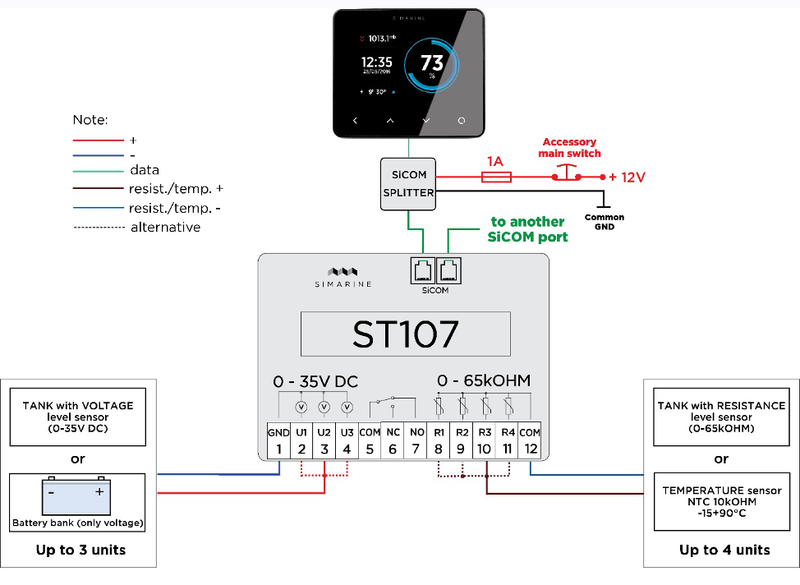
If you have a PICO monitoring system installed or switching passes through special control panels, then the manual describes in detail the setup and calibration process.
3. How often should the tank level module be calibrated?
Calibration should be performed during the installation of each new tank in the monitoring system, in case of adding new modules with reconnection of sensors, replacing or adding sensors, as well as in case of incorrect level measurement. This is a simple operation.
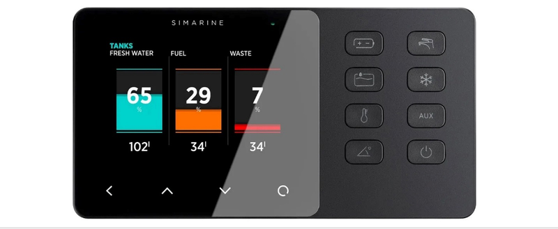
Here is an example of tank calibration using the SCQ25T or ST107 module. In the PICO monitoring system, the configuration of these modules for measuring the level in fuel and water tanks is identical.
After long pressing the enter button into the settings menu, go to DEVICES > TANKS, then select "Add New" and fill in the requested data according to the following guidelines:
- NAME – name the tank appropriately (FRESH WATER, WASTE WATER, FUEL 1, etc.)
- TYPE – indicate the type of tank: for water, fuel, waste.
- SENSOR TYPE – indicate the type of sensor used (RESISTANCE or VOLTAGE)
- DEVICE – select the sensor to be used from the list provided.
- CAPACITY – enter the capacity of a full tank.
- CALIBRATION POINTS – Add calibration points for different tank levels, there should be at least two. But if you want the system to show more correct measurements, add a few more calibration points.
- Confirm and save the tank configuration using the button with the < icon
This should be done with each tank that is connected to the monitoring system.
4. What can cause loss of communication between the tank level module and the control system?
The most likely reason is disconnection during operation, initially incorrect installation of the module, errors during calibration, due to which the control system display or the entire control system does not see the tank level module.
All connections of existing sensors should be checked, their compatibility with the inputs, correct polarity and correct calibration.
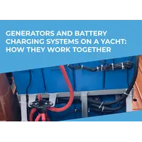
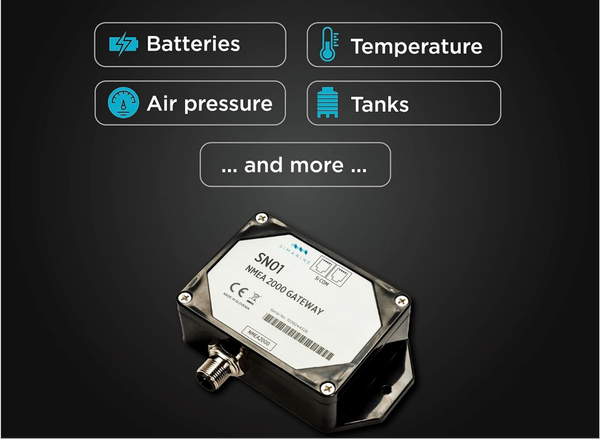
For better communication between the module and the control system, we recommend using the NMEA2000 protocol where possible. In Simarine monitoring systems, this opportunity is provided by the innovative module SN 01 NMEA 2000 gateway, which ensures communication of all electrical and electronic equipment of the yacht with the exchange and transmission of data to the display.
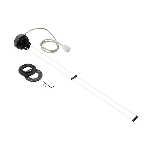
5. How to solve the problem with a stuck or broken mechanical float sensor?
Float sensors are actively used to measure the level of both water and fuel tanks when it comes to marine and road transport.
The maximum permissible error in the fuel level sensor readings is 1%. Today the following types of float fuel level meters are produced:
- lever - the float is connected to the contact using a metal lever, which allows them to be used in different types of fuel tanks;
- tubular - the float is placed inside a hollow tube, due to which it does not come into contact with the fuel. The float and lever are connected using a magnet, which moves along a sector with metal plates. As a result, a magnetic field is created, which generates a signal about the available volume of fuel. The main advantage of the device is a high level of resistance to vehicle vibrations.
As for floats, they can be of two types - hollow (made of metal or plastic) or made of porous material. The first type is most susceptible to damage, which leads to incorrect fuel level sensor readings. The solution to the problem in this case is to replace the float.
Incorrect fuel level sensor readings are the main sign that this device is not working. As a result of mechanical damage, the hollow float fills with gasoline, causing the sensor to deviate more and more from the correct readings.
Both porous and hollow floats can face another problem - sticking due to damage to the tank. In this case, either one value is shown on the instrument panel, or the readings vary within a small range. The solution to the problem of incorrect fuel level sensor readings in this situation is to replace the fuel tank.
6. What action should be taken if the ultrasonic sensor does not read the liquid level correctly?
When using an ultrasonic liquid level sensor, false values obtained during measurement may occur. These can be surges when the tank is empty and dips when the tank is full.
The reasons for false readings when the tank is empty can be both the design features of the tank and the location of the sensor. When the liquid level is low, the energy of the ultrasonic pulse is not dissipated and is expressed as noise, which can be perceived by the sensor as a false level value. In some cases, gluing a noise-insulating layer around the sensor may help.
If possible, you should use a software technique, which consists of tuning out noise using special programs.
There is also a method for eliminating failures when the tank is not empty. The ultrasonic level sensor makes measurements using the echolocation method in the following order:
- the sensor generates an ultrasonic radio pulse into the measured medium and begins counting the time of flight;
- a radio pulse propagates in a medium at the speed of sound characteristic of a given medium;
- upon reaching the liquid-gas interface, reflection occurs and the radio pulse propagates in the opposite direction to the sensor;
- upon reaching the sensor, the radio pulse is registered by an electronic circuit, and the time-of-flight counting stops;
- the resulting time is proportional to the distance from the bottom to the surface of the liquid reflections on the operation of the sensor, the sensor emitter is designed to be highly directional. Because of this, when the sensor axis deviates from the vertical, it “goes blind” - the reflected ultrasonic radio pulse does not reach the sensor and the sensor produces a zero level value. This most often applies to moving in a heeled state on a yacht or stopping in a car on an incline.
This problem can be solved in two ways:
- by filtering of zero values in the monitoring program;
- by changing the sensor configuration - prohibiting the zero value or allowing it after a certain set time.
7. What interference and interference minimization techniques can be used for hydrostatic sensors?
The operating principle of hydrostatic sensors is based on measuring the pressure of a liquid column, the height of which is equal to the height of the liquid level in the tank.
It is assumed that the density of the liquid whose pressure it measures will be constant - the one for which it is calibrated by the manufacturer. But changing the fuel can actually change this figure. For example, the density of diesel fuel is different from that of gasoline. Density can also change due to temperature changes. On average, for gasoline and diesel fuel this change is 0.7 kg/m3 for every additional 10 degrees.
The density of wastewater can also differ from the density of fresh and sea water.
These seemingly small deviations can become a big problem. It is therefore important to initially evaluate the possibility of such changes taking into account the density of the fuel, water and tank geometry and decide on its acceptability.
To improve control, level sensors can be used in conjunction with temperature sensors, pressure sensors or even a wastewater adapter if we are talking about a large vessel.
8. How to determine that a capacitive sensor needs to be replaced?
The operating principle of such sensors is based on the fact that liquids and the gas space above them have different electrical properties.
The capacitive level sensor can be connected digitally or analogue using an isolated CAN bus and controller. A two-wire connection circuit is also used, allowing continuous monitoring of the liquid level. In addition, some models can be installed using a pipe attachment or with a cable probe.
Since capacitive sensors’ measurement product serves as an insulator-dielectric, for accurate work, the devices can only be installed in containers with metal walls, and the wall where the fastening will be performed must be located strictly parallel to the probe.
After connection, a test run is performed, calibration is carried out on a completely empty and completely filled container.
Signs of a capacitive level sensor not working or not working correctly are a lack of measurement data or clearly incorrect readings. This may be caused by improper calibration, installation or connection of the sensor.
If the technical inspection does not reveal any violations of the installation, calibration and connection processes, the inoperative capacitive sensor requires replacement.
9. How to eliminate condensation and contaminants that affect the operation of tank level sensors?
Very often, the cause of incorrect tank level measurements can be condensation and contamination. Above we talked about how changes in liquid density affect the performance of hydrostatic sensors. But the characteristics of the measured liquid can also change due to condensate constantly entering the boat’s fuel system. The density of the contaminated liquid will also change if, for example, the cleaning filter fails and untreated sea water enters the tank.
Therefore, if you notice suspicious indicators of the level of water tanks, before checking the sensors and monitoring system, check the operation of all installed filters and, if necessary, replace them, starting from the primary filter and ending with the fine filter. Of course, the tanks should be thoroughly washed before refilling, especially with potable water.
With the yacht's fuel system, everything is much more complicated. Moisture gets inside the fuel tank during refueling through the filler neck. Moreover, the higher the air humidity, the more of it will get in during one refueling. Water is heavier than gasoline, so when it condenses, it settles to the bottom of the fuel tank.
We will not discuss poor quality gasoline as the cause of water in the fuel system.
What to do if water has already entered the fuel tank, and the owner of the outboard motor found out about this after the fact - the engine does not start well, runs intermittently, or stalls at idle?
The answer is simple - water must be removed from the fuel system. The practical implementation of this is already more difficult. The fact is that you will not have to remove it from the fuel hoses at all - water, as a rule, does not accumulate there at all, except in very advanced cases.
First you need to drain the fuel from the fuel tank and get rid of the water in it. We remind you that there will always be water at the bottom. And the fuel, no matter how much there is, and no matter how sorry it is, will have to be sent for disposal.
When we talk about water in this context, we mean, of course, not pure or distilled water, but a mixture of water with impurities.
Next, we remove, disassemble and thoroughly clean/bleed the fuel pump. If some of the contaminants remain in any component, after starting the engine it will spread throughout the entire fuel system, it will settle somewhere else, and everything will have to start over.
The same procedure must be carried out with the carburetor(s) on those models that, of course, have them. Keep in mind that after disassembling this unit, all adjustments and synchronization will need to be done again. Therefore, if you are not confident in your own abilities, it is better not to take on this, but contact the service center immediately.
For modern 4-stroke engines equipped with an injection system, it is also necessary to diagnose the injectors. If water gets into them, be sure to clean them. Of course, all fuel filters must be replaced.
10. What should I do if the tank level module stops sending data to the display?
If the tank level sensor is not visible on the display, you should check the following parameters:
- the tank level module is correctly connected via the SiCOM port to the battery monitor or control panel;
- correct use of your own SiCOM cable (see table above);
- resistance/voltage sensor compatibility;
- connecting the tank sensor to the correct input resistance or voltage sensor;
- calibrating the tank sensor through the system menu;
- sensor coverage of the entire tank level.
As you test your tank sensors, you should be prepared to recalibrate your tank sensor(s) or replace one that is stuck or not working. Sometimes the sensor can get stuck due to violations of the integrity of the tank, then the tank itself must be replaced if repair is impossible.
A float sensor that is too shorted may not cover the entire liquid level in the tank and may indicate an empty tank at a certain level. Replace such sensor with a suitable one.